When commissioning 3D scanning services, its crucial to know what the “downstream” application will be. Will the 3D data be used for reverse engineering? 3D printing? CNC milling? Visualization? FEA or CFD? While some downstream applications are more forgiving than others, one thing is clear: Getting the best high quality 3D scan data available will greatly increase your chances for success.
In general, medium to large size, “soft”, organically shaped objects are the easiest to scan. Objects with sharp edges, and/or small features – including the majority of industrial objects – are much more challenging and require higher quality hardware and more experienced operators. These are among the projects that simply can’t be done in a satisfactory manner with low end scanners.
Scansite 3D uses aerospace certified structured light scanners manufactured by GOM/ATOS and Aicon/Breuckmann, as well as the entire suite of Creaform 3D scanners, and Aicon3D Photogrammetry systems. We have top quality hardware and software, and experienced, talented people doing our scanning, and we are proud of the 3D data we produce.
It often happens that we see 3D data produced by other people using other scanners. Frankly, we are often surprised at the poor quality of some of this data and what apparently passes as “standard” in our industry. I’ve concluded that the majority of the consumers of 3D data don’t really know what good and bad data looks like, and what they can expect to receive for their money.
Hence the mission of this blog edition – the first in an ongoing series – is to show examples of high quality versus poor quality scan data – and hopefully educate the 3D data consuming public.
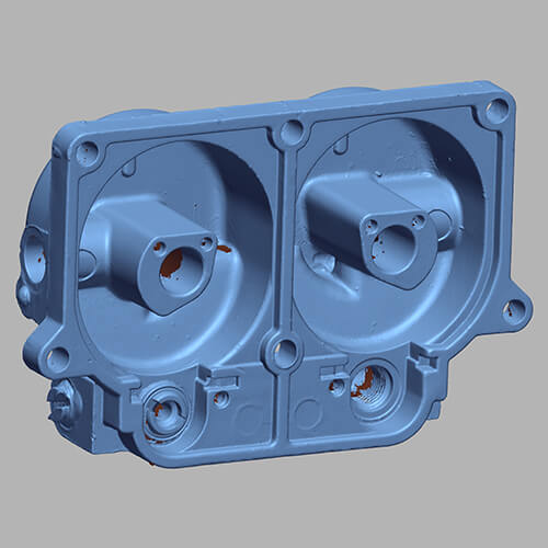
Below are two examples of 3D scan data. Both are computer screen shots of .stl (polygon mesh) 3D scan data. Please “click to enlarge” these screen shots to get a good look at the quality of the data.

“Industry standard” 3D scan data (Click to enlarge) . This 3D data was professionally scanned using a mid-range, non-structured light scanner. Note the softness of the features. The screw heads and other features appear to have “melted”.

Structured light scanned data (Click to enlarge) . This automobile carburetor was scanned at Scansite 3D’s studio using a Breuckmann StereoScan “white light” (or “structured light”) scanner. Note the crispness of the screw heads. Sharp edges remain sharp.
If this data is used for building a CAD file in reverse engineering software, our engineers can be confident that the resulting geometry will be accurate within precise tolerances.
Finally, let’s suppose that the “downstream” application for the two data sets shown above is reverse engineering. The CAD engineer will attempt to build a CAD file by extracting features from the scan data. Which data set would yield the more accurate CAD data? You decide!


