Types of 3D Files Available From Scansite3D
There are several types of 3D files available as deliverables from Scansite3D. Which 3D file type (format) works best for your project will depend on several factors, including;
(1) What is the intended “downstream” use for the file (3D printing? Inspection? Design changes using CAD software?
(2) What software will be used to achieve the desired result? If the file is going directly to a 3D printer, then this may not be important. But if the user wants to import the file into a downstream CAD software package, then the type of 3D file format becomes very important. For example: An .stl file format may be perfect if the final downstream use is 3D printing, but of limited functionality when imported into CAD software such as Solidworks.
Cost: There are substantial differences between types of 3D “Deliverables”. For example, a “Natively Parametric” CAD file costs more than a point cloud (raw 3D scan data).
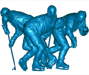
1. Point Cloud or “Non-Watertight” Polygon Mesh
Description: This is the “raw” data produced by most 3D scanners, and thus, at this stage, has not required extensive editing.
Uses: Inspection; CAD creation in some software packages such as Geomagic DesignX®.
Pros: Generally the least expensive option and adequate for many uses.
Cons: Additional editing/processing usually required for use in other applications such as 3D printing.

2. “Watertight” Polygon Mesh
Description: This is a polygon mesh that has been edited in order to make it “watertight”. It is most commonly delivered in .stl or .obj format.
Uses: 3D Printing, CNC milling, and some types of CAD creation software including Geomagic Studio® and PolyWorks Modeler®.
Pros: The “Watertight” quality is essential for many applications.
Cons: Limited functionality when imported into most CAD packages (i.e. Solidworks®).
3. CAD format (STEP, IGES & X_T) Using “DESIGN INTENT” Method
Description: CAD friendly file. At Scansite3D we create these with Geomagic DesignX® software. The “Design Intent” modeling method is used.
Uses: CAD files can be imported into all major CAD packages, including SOLIDWORKS®, Siemens NX®, Solid Edge, Autodesk Inventor®, PTC Creo® and Pro/ENGINEER®.
Pros: Universally accepted by all CAD packages.
Cons: Costs more than scan data (#1 or #2 above). Does not have a “feature tree” like a “natively parametric” CAD file.

4. CAD format (STEP & IGES) Using “EXACT SURFACING” Method
Description:
Uses: CAD files can be imported into all major CAD packages, including SOLIDWORKS®, Siemens NX®, Solid Edge, Autodesk Inventor®, PTC Creo® and Pro/ENGINEER®.
Pros: Universally accepted by all CAD packages.
Cons: Often costs more than scan data (#1 or #2 above). Does not have a “feature tree” like a “natively parametric” CAD file.

5. CAD format (STEP, IGES & X_T) Using “DESIGN INTENT” Method
Natively Parametric Files available for SOLIDWORKS®, CATIA® & PTC Creo®
Description: CAD friendly file. At Scansite3D we create these with Geomagic DesignX® software. The “Design Intent” modeling method is used.
Uses: CAD files can be imported into all major CAD packages, including SOLIDWORKS®, Siemens NX®, Solid Edge, Autodesk Inventor®, PTC Creo® and Pro/ENGINEER®.
Pros: Universally accepted by all CAD packages. Available as a “Native” file (with Feature Tree) for SOLIDWORKS®, CATIA®, and PTC Creo®.
Cons: Cost more than scan data (#1 or #2 above).
